5 Tips to Get Better at Automotive Diagnostic

5 Tips to Get Better at Automotive Diagnostic
5 Tips to Get Better at Automotive Diagnostics
Since becoming an automotive technical trainer in 2010, I've had the privilege of training thousands of technicians on effective diagnostic techniques. Through this experience, I've noticed some of what the best diagnostic technicians do to make them successful in completing diagnostic jobs. In this blog, I'm going to share five tips that you can start using immediately to enhance your automotive diagnostic skills.

TIP 1: Refine Your Diagnostic Process
When asked about their diagnostic process, many technicians typically start with, "We plug in the scan tool and read the fault codes." But then if you say, “Well, what about if it was a knocking noise from the rear or what if it was a water leak?” or something like that, then that gets them thinking about what a diagnostic process is. At Mechanic Mindset, we follow a diagnostic process that we call FIXDIT, where each letter stands for a step in the process.
There are actually two steps that we want to perform before we actually start ripping the car apart and probing wires with our multimeter and things like that. Before we actually start doing anything, we're going to want to collect as much information as possible and there's a lot of information that you can collect as soon as you start going out to the vehicle.
Take a typical Non-Start Fault; when you unlock and open the door you might hear the fuel pump primes. Now you know that that part of the system is working. Even simply unlocking the door is telling you that a large portion of this vehicle system is operating as it should be. And then of course, we're going to switch the ignition on and try and crank it over. The very act of turning it on and cranking it over is telling you that there's lots of things that are working. Take the rev counter for example. If you notice the needle moves when you crank it, it shows us that not only is the engine speed sensor working but the engine management system is putting that signal onto the CAN bus network and that signal is making its way up to the instrument cluster.
After you've gone ahead and took the time to find all this evidence, you then need to sit down and put it all together ultimately to get you to a point where you're going to make your first test. And hopefully, it's in the the right place.
Click here to claim your free FIXDIT diagnostic process poster. (Print it and display in the workshop!)

Following the FIXDIT Diagnostic Process will help you save time, earn more money, and keep your customers happy.
TIP 2: Master Electrical Diagnostics
Electrical diagnostics is often considered the most challenging aspect of vehicle repair. However, those who excel in this area have a firm grasp of the basics. By mastering these fundamentals, you'll be more proficient in electrical diagnostics, leading to quicker and more accurate repairs.
Here are some tips to help you improve your electrical diagnostic skills:
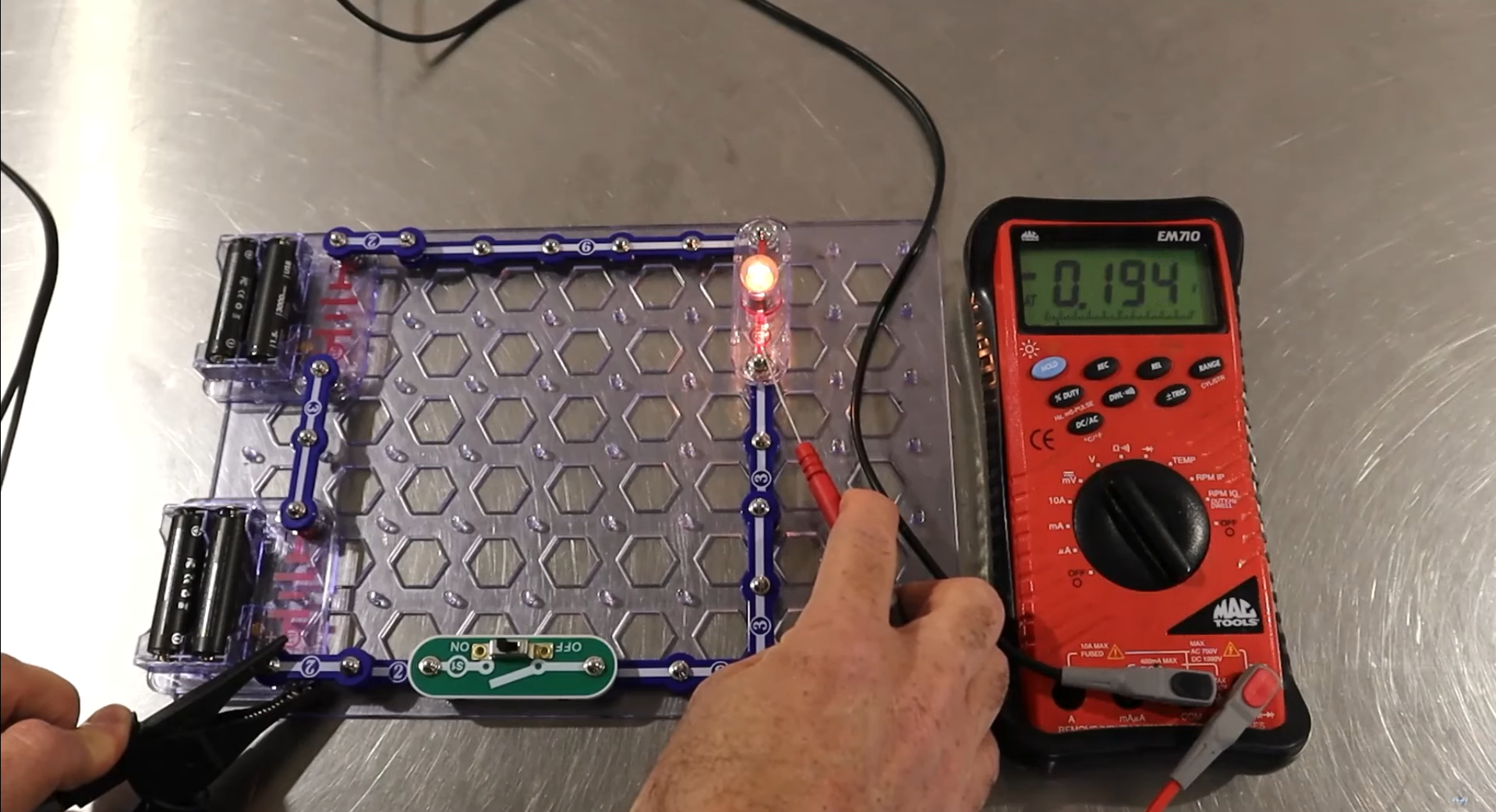
The multimeter is a difference measuring tool. It measures the difference between two points. For instance, when measuring battery voltage, place the black (negative) lead on the ground (0 volts) and the red (positive) lead on the battery’s positive terminal. If the battery voltage is 14.2V, the multimeter shows a reading of 14.2V because it measures the difference between the 0V on the ground (black lead) and the 14.2V on the positive terminal (red lead).
Do all your testing with the circuit switched ON: Always perform electrical tests with the circuit switched on. An unloaded circuit can give inaccurate readings. For example, if there is a resistance in the power supply, you will still measure battery voltage at the consumer when it’s switched off!
Live Side Testing: Connect the black lead to the ground and measure the voltage at different points in the circuit. For example, if the power supply reads 5.64V and the bulb reads 5.45V, there's a voltage drop of 0.19V. This indicates a minor loss or voltage drop, which is acceptable.
Ground Side Testing: Similar to live side testing but focusing on the ground. The voltage should be as close to zero as possible when the circuit is on. A significant voltage indicates a poor ground connection.
Zero volts is different to nothing. When testing grounds, ensure you understand the difference between zero volts and ‘nothing’. A stable reading near zero volts indicates a good ground. But if you connect up to a lead and the numbers on the meter are fluctuating near zero, it indicates that the wire might not be connected to anything at all (neither positive or negative).
Voltage Drop Limits: A maximum voltage drop of 0.5V is acceptable. For example, in a 12.5V circuit, the power supply should be no less than 12V, and the ground should be no more than 0.5V. But always take the readings with a bit of logic. Sometimes you would have a slightly higher reading but the system might still be working okay.
The “green crusties” (corrosion): If the bulb is dim and the voltage drops significantly when the circuit is on, there's likely corrosion on the power side. If the ground shows a significant voltage instead of close to zero, there's an issue on the ground side.
Sign up to the Free Training Area on Mechanic Mindset - we have some lessons on electrical testing for you to learn more.

Switch the circuit ON before you do any testing so you wouldn’t miss any other faults in the circuit.
TIP 3: Understand Sensor Circuits
Once you understand the basics of how a sensor circuit works, the majority of sensor diagnostics becomes very very easy. Most sensor circuits work on the principle of a voltage divider circuit. Knowing the fundamentals of how a voltage divider circuit works can help you diagnose issues with sensors effectively.
Basics of Sensor Circuits
Voltage Divider Circuit: This is important to understand sensor circuits. A basic voltage divider involves two resistors in series between a power supply and ground. In the middle of the circuit, the voltage should be half of the supply voltage if the resistors are equal. And since most of the sensor circuit operates at 5V (but not all), you should expect to see half the voltage which is 2.5V.
Control Unit and Sensors: In real automotive applications, parts of the voltage divider are inside the control unit, and the sensor acts as a variable resistor, changing the voltage based on the measured parameter.
Working of a Sensor
Pull-Up and Pull-Down Resistors: A pull-up resistor has 5V on one side and is connected to the sensor, which alters resistance to change the voltage signal read by the control unit.
Variable Resistor Example: For a temperature sensor, as temperature changes, the resistance changes, altering the voltage signal to the control unit, which interprets this change to determine the temperature.
Sensor Voltage Range
Operating Range: Sensors typically operate within a range (e.g., 0.5V to 4.5V for a 5V system). If the signal goes outside this range, it indicates a fault.
Fault Codes:
Signal Too High: Voltage exceeds the upper limit.
Signal Too Low: Voltage drops below the lower limit.
Diagnosing Faults
Open Circuit: If the sensor circuit is open, the voltage jumps to the supply voltage, indicating a fault (e.g., 5 volts for a 5-volt system).
Short Circuit to Positive: If the circuit is shorted to the positive supply, the voltage again reads the full supply voltage.
Short Circuit to Ground: If shorted to ground, the voltage drops to zero.
Practical Example
Fuel Pressure Sensor: If a sensor is disconnected, the signal might jump to the supply voltage (e.g., 5V), triggering a "circuit high" fault. Conversely, if shorted to ground, the voltage drops near zero, triggering a "circuit low" fault.
Implausible Signals: Faults also occur when signals are outside expected ranges based on operating conditions. For instance, temperature sensors should reflect ambient temperatures when the vehicle is cold. Deviations can trigger fault codes like "signal out of range" or "signal implausible."
Sign up to the Free Training Area on Mechanic Mindset - we have some lessons on electrical testing for you to learn more.

Understanding the voltage divider circuit and how sensors interact with the control unit is crucial for effective diagnostics.
TIP 4: Familiarize Yourself with Live Data
Live data analysis is crucial, but many technicians struggle with interpreting it. They say, “How do I know what it's supposed to be?” or “How do I know if that reading is correct?” Now, there's no real good answer for that other than that you need to get to know it yourself and understand what kind of signals and data you should be seeing on those similar types of engines because they're all pretty similar. So a 2L petrol on an Audi, you're going to get similar readings to a 2L petrol on a BMW.
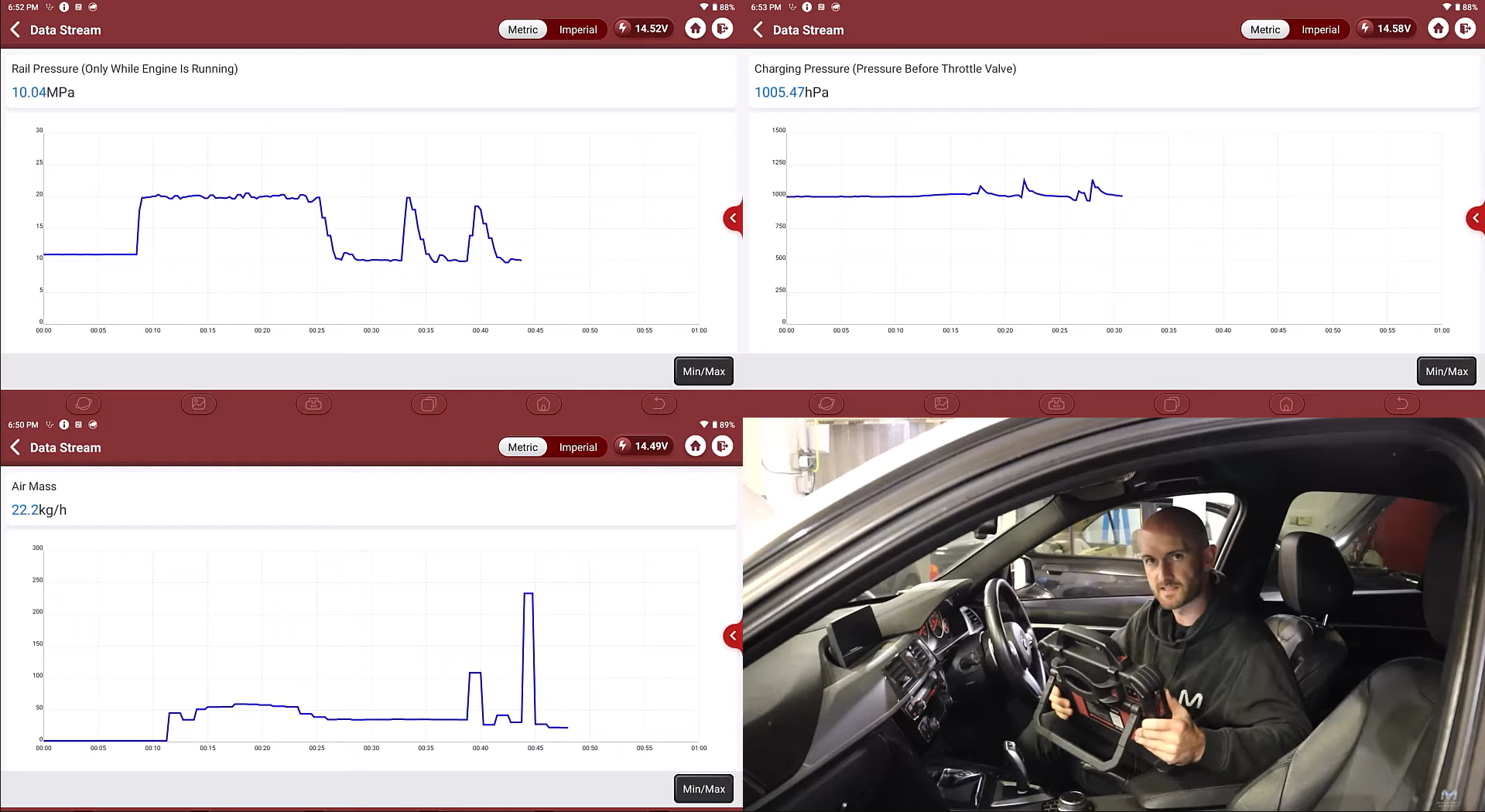
Spend time learning what normal readings look like for various sensors and you're not going to have to take hours and hours out of your work schedule to do this. If you've already got the tool plugged in for a diagnosis on a different problem or a service or something like that, just take one or two minutes just to have a quick look at it and store it in your memory bank.
For instance, take note of air mass meter signals, manifold absolute pressure sensors, and fuel pressure readings on different vehicles you work on. Observe the signal when the ignition is on, during cranking, at idle, and under load. Building this knowledge base will help you quickly identify abnormal readings and diagnose issues more efficiently. We're trying to build a library of known good data inside Mechanic Mindset. You can go and check it out and see if it car relates to what you've got.
Sign up to the Free Training Area on Mechanic Mindset - we have some lessons on electrical testing for you to learn more.

Have a look at the data under different operating conditions: when the ignition is on, during cranking, at idle, and under load.
TIP 5: Get Comfortable with Wiring Diagrams
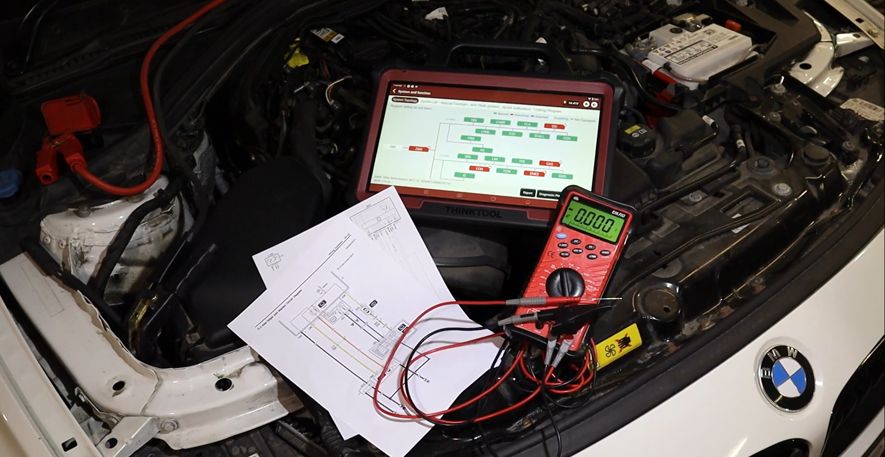
Interpreting wiring diagrams is a crucial skill for any diagnostic technician. Good information is the foundation of successful diagnostics. So whenever possible, use OEM wiring diagrams as they provide the most detail, including wire colors, sizes, and signal types. Personally, I use wiring diagrams from AllData.
When reading diagrams, start by identifying and highlighting all power supplies and grounds on the diagram. This helps in tracing circuits and understanding their paths. Follow the connections from components like junction boxes and relays.
Get familiar with wire codes. Take BMW wiring diagrams as an example. They use U for power supplies, M for grounds, A for analog signals, and T for timed or pulse width modulated signals. Also note the wire thickness. Power and ground wires for actuators are typically thicker than those for sensors.
To get the most out of wiring diagrams, practice reading and interpreting them regularly. Over time, you'll develop an intuition for how different systems are wired and how to troubleshoot them effectively.
Sign up to the Free Training Area on Mechanic Mindset - we have some lessons on electrical testing for you to learn more.

When reading diagrams, I start by highlighting definite connections, such as power supplies and grounds.
By following these 5 tips, you can significantly improve your diagnostic skills and become more efficient in identifying and solving automotive issues.

