Test Your Sensor Systems with the ProLogics Probe - Here's How!

Test Your Sensor Systems with the ProLogics Probe - Here's How!
Test Your Sensor Systems with the ProLogics Probe - Here’s How!
In this blog, we look into the ProLogics Sensor Simulator Probe, an essential tool for diagnosing sensor issues in engine management systems. From testing voltage to simulating signals, this device is packed with features that make it a must-have for anyone troubleshooting sensor circuits. We'll cover what’s included, how it works, and a few of its standout features.

What’s in the Box?
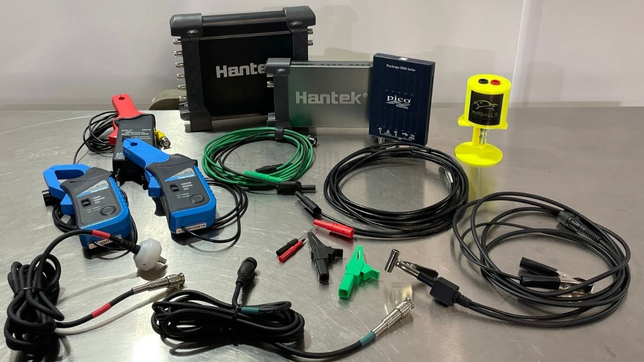
Inside the box, you’ll find the probe itself, a power supply cable, a remote ground lead, an alligator clip, and a smaller remote alligator clip. The probe connects with 4mm banana-style connectors, making it compatible with the ProLogics Sensor Test Lead Kit and other diagnostic accessories.
Check out the Diagnostic Coach program here.
Key Features of the Probe
Voltage Simulation
Connecting the probe to a battery powers it up. A useful torch function is available via a button. In voltmeter mode, the probe measures voltage as a typical voltmeter would. Switching to simulation mode allows testing of reference voltages, with an on-screen warning to confirm proper polarity.
The probe can simulate sensor voltages up to 12V. With both a 150mA mode for signal circuits and a 3A mode for power supplies, it’s suitable for a variety of tests, compatible with 12V and 24V systems.
Frequency Output
The probe offers both AC sine wave and digital square wave signal outputs. The square wave can be configured for positive or negative switching, which makes it useful for pull-up or pull-down resistors in control modules. Frequency is adjustable using arrow buttons, with changes visible on an oscilloscope. This function is ideal for testing inductive sensors like wheel speed and crankshaft position sensors.
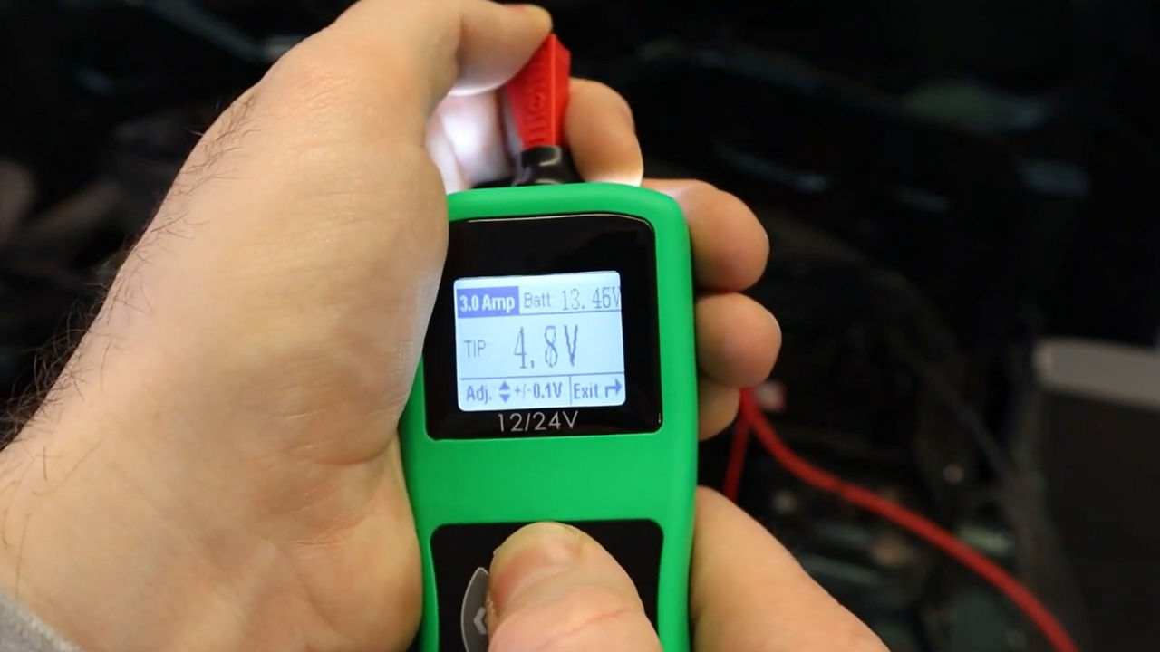
The probe allows fine-tuning of voltage in 0.1V increments and frequency adjustments, which enables mechanics to simulate various sensor states and observe them on an oscilloscope.
Diagnosing Fault Codes
We connected breakout leads to a camshaft position sensor, isolating the ground and signal while disconnecting the power. A 5V power supply from the probe was used to clear an inlet camshaft sensor fault code, confirming circuit integrity if the code remains cleared after cycling the ignition. If the issue persists, it may indicate wiring problems.
PWM Simulation
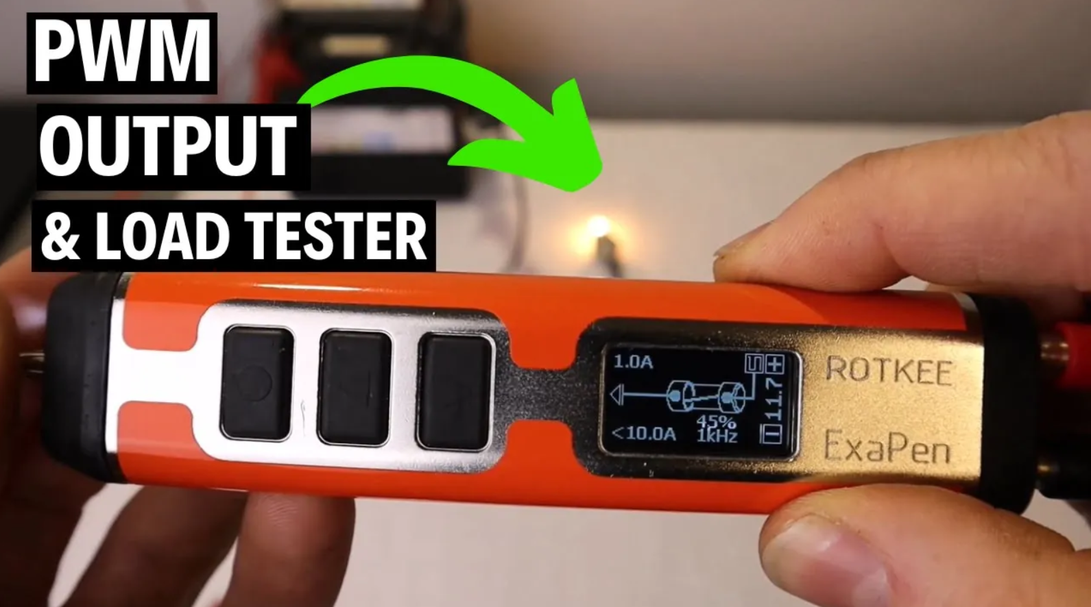
The probe replicates duty cycle signals needed for intake air temperature sensors found in combined MAF (mass airflow) and temperature sensors, among others. This feature allows you to test various sensors that rely on pulse-width modulation for accurate readings. It can also supply power up to 3 amps in PWM mode.
Variable Ohm Setting for Resistance Testing
This feature enables resistance variation, crucial for testing sensors like coolant temperature sensors. The probe allows for ranges between 100-10,000 ohms, letting you simulate the entire spectrum of temperature sensor responses by adjusting resistance. This can be particularly helpful for evaluating NTC (negative temperature coefficient) sensors, commonly found in air temperature and coolant sensors.
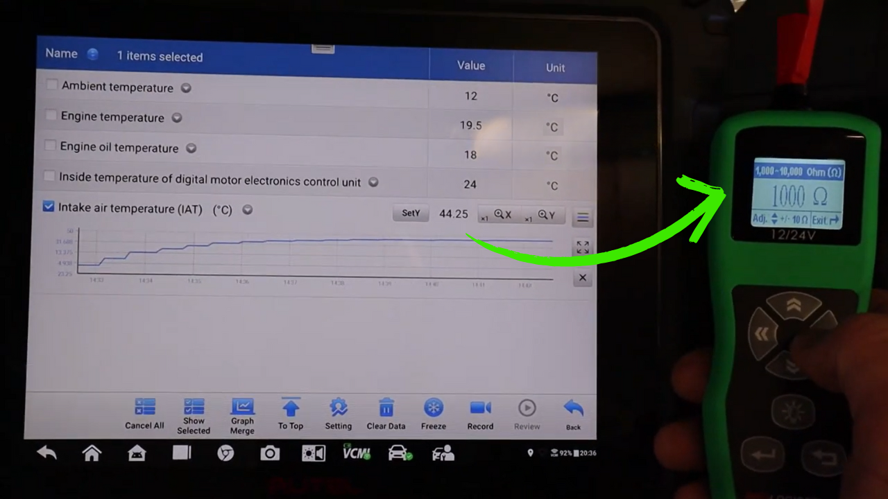
After setting up as the intake air temperature sensor, adjusting the resistance yielded real-time temperature changes.
How to Use the ProLogics Sensor Simulator Probe
To demonstrate, we tested a 5V camshaft position sensor. By connecting the simulator probe, we fed a 5V power supply to the sensor, effectively bypassing the broken circuit. This allowed us to clear the fault code and confirm that the sensor was operating correctly, guiding us to check the wiring or control module for faults.
The probe’s frequency function was tested on a crankshaft sensor. By increasing the frequency, we observed how RPM values responded on the scan tool, mimicking an engine running at different speeds.
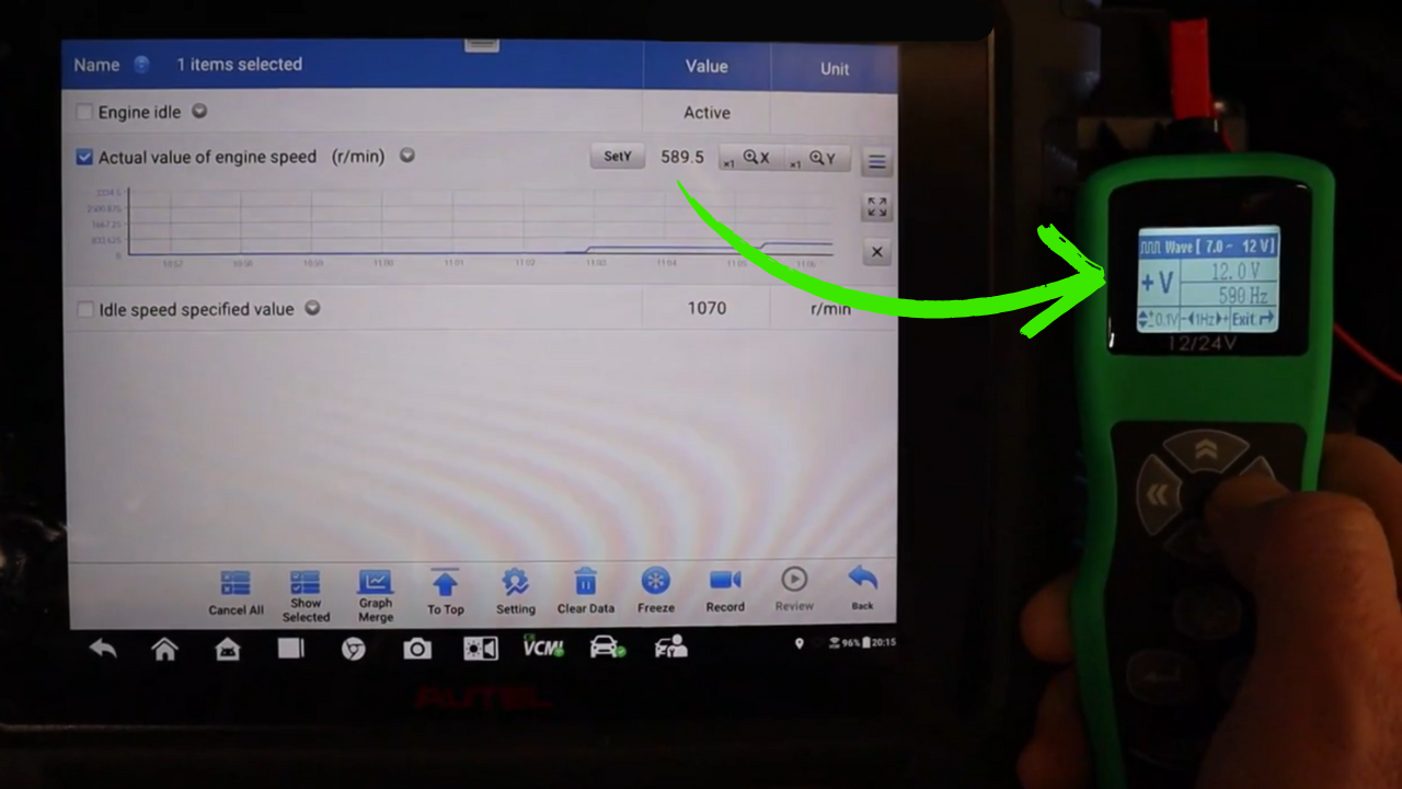
By increasing the frequency, we observed how RPM values responded on the scan tool, mimicking an engine running at different speeds.
Practical Applications for You
The ProLogics Sensor Simulator Probe is a versatile tool for mechanics and diagnosticians. Whether you’re testing voltage or diagnosing signal issues, it simplifies troubleshooting sensor circuits. Its capability to simulate various signals lets you systematically eliminate possible faults, saving time and providing clear insights into engine management systems.
Unlock the secrets of Sensor Diagnostics with Mechanic Mindset’s in-depth course! Designed for technicians of all skill levels, this course takes you from the basics to advanced diagnostic techniques, giving you the knowledge to confidently troubleshoot sensor issues on engine management systems.
Join our Diagnostic Coach program.
With easy-to-follow lessons, hands-on practice, and expert guidance, you’ll learn to work with everything from reference voltages to complex signal simulations, enhancing your skills in no time.

